EyeTrackVR / Unity
Affordable VR Eye-Tracking Add-on for Research
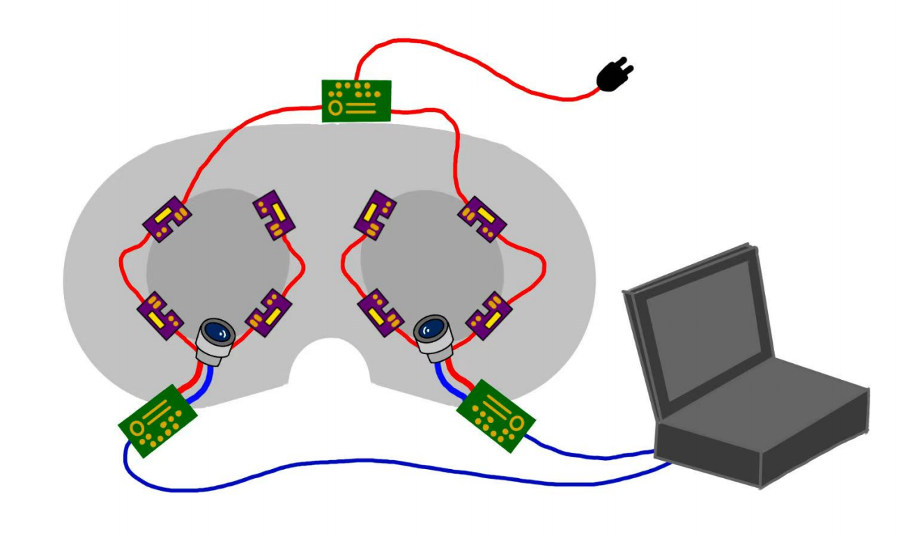
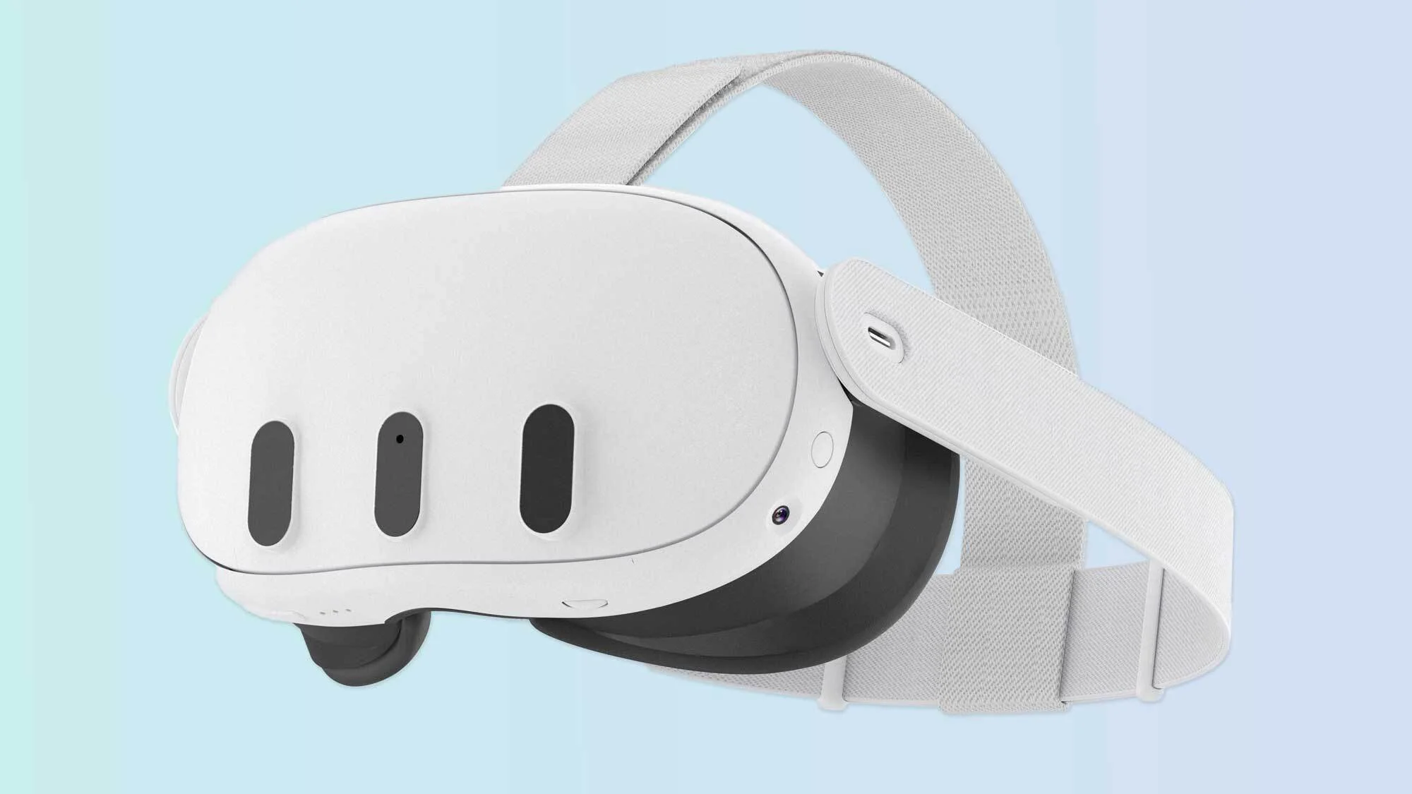
Figure 1: The hardware modification on a non-eye-tracking VR headset.
Overview
This project presents a cost-effective eye-tracking solution (hardware + software) designed to upgrade a standard non-eye-tracking VR headset (e.g., Meta Quest 3) into an eye-tracking compatible research instrument at a fraction of commercial solutions' cost. The system achieves an average tracking accuracy of 4.8° of visual angle with a refresh rate of 60 Hz, making it suitable for specific research applications including attention studies, interaction technique development, and gaze analytics.
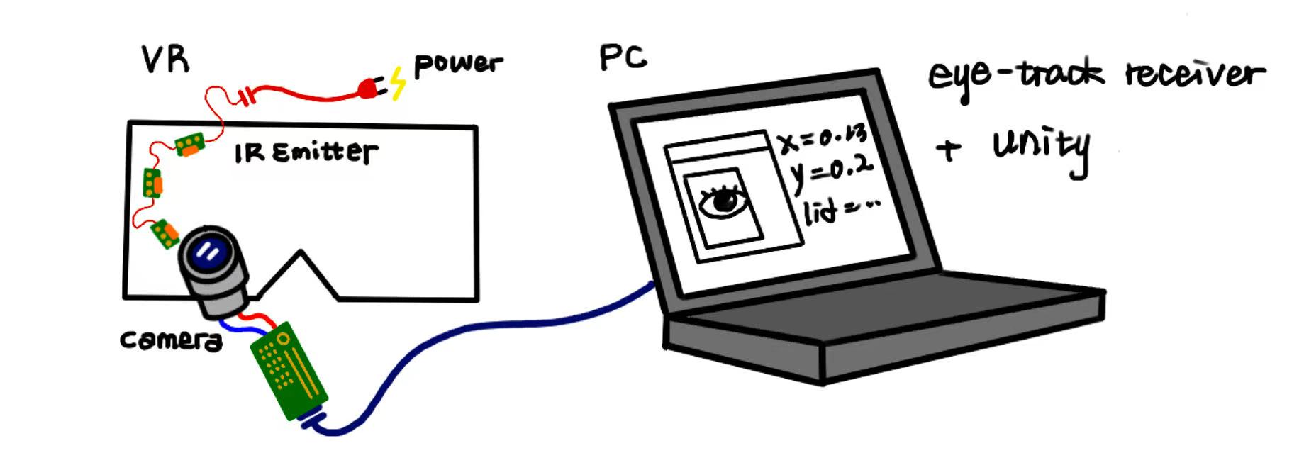
Figure 2: A simplified illustration of the hardware setup and overall data flow.
Motivation
Eye tracking represents a critical component in VR research, enabling analysis of user attention patterns, interaction behaviors, and enabling foveated rendering. However, commercial eye-tracking solutions present significant barriers to entry:
- High Cost: Professional VR headsets with integrated eye-tracking (e.g., Varjo XR-3, HTC Vive Pro Eye) typically cost between $1,500-$6,500, placing them beyond the reach of many research budgets and educational institutions.
- Limited Accessibility: Many eye-tracking solutions require proprietary software ecosystems or specialized hardware environments, limiting flexibility in research design.
- Data Ownership: Commercial platforms may impose restrictions on raw data access or implement "black box" processing algorithms, limiting research transparency.
- Educational Barriers: Students and early-stage researchers often lack access to expensive equipment needed to gain hands-on experience with eye tracking technology.
This project aims to demonstrate that an affordable eye-tracking solution ($200-300 total build cost) can serve as a practical alternative for educational environments and exploratory research, while providing students with valuable hands-on experience in computer vision and hardware integration.
Results Overview
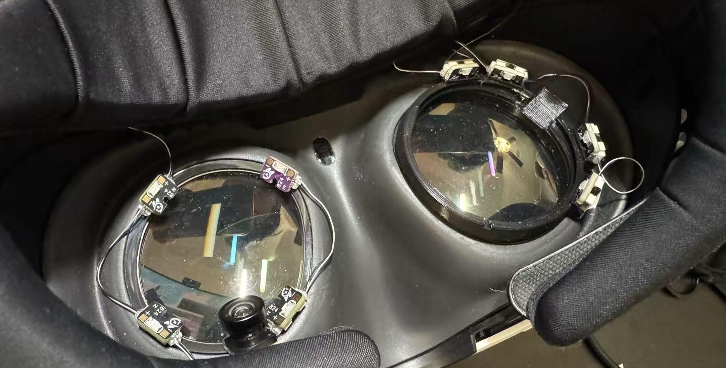
Figure 8: The final build of the VR eye tracking hardware system (image placeholder).
- Sampling Rate: ~60 Hz (wired configuration offers higher stability than wireless)
- Accuracy: 4.8° visual angle (SD = 1.8°)
- Latency: ~20-50 ms (varies by configuration)
- Data Output: Real-time gaze vectors, eye openness, pupil diameter
- Data Format: OSC (Open Sound Control) protocol for easy integration
- Total Cost: ~$280 for hardware (excluding VR headset)
Note: These specifications were measured in April 2025 using the wired configuration.
Practical Discrimination Capabilities
The 4.8° accuracy translates to different real-world discrimination abilities:
- Virtual Desktop (50cm): ~4.2cm discrimination - suitable for larger UI elements like app icons or menu sections
- Arm's Length (1m): ~8.4cm discrimination - ideal for detecting focus on larger objects in near-field environments
- Far Display (5m): ~42cm discrimination - appropriate for determining which section of a large virtual display receives attention
Required Parts
This project builds upon the open-source EyeTrackVR project. Comprehensive assembly guides and technical documentation can be found in their official documentation.
Core Components
Screenshot - Click to enlarge
A non-eye-tracking VR headset (e.g., Meta Quest 3, ~$499)
Screenshot - Click to enlarge
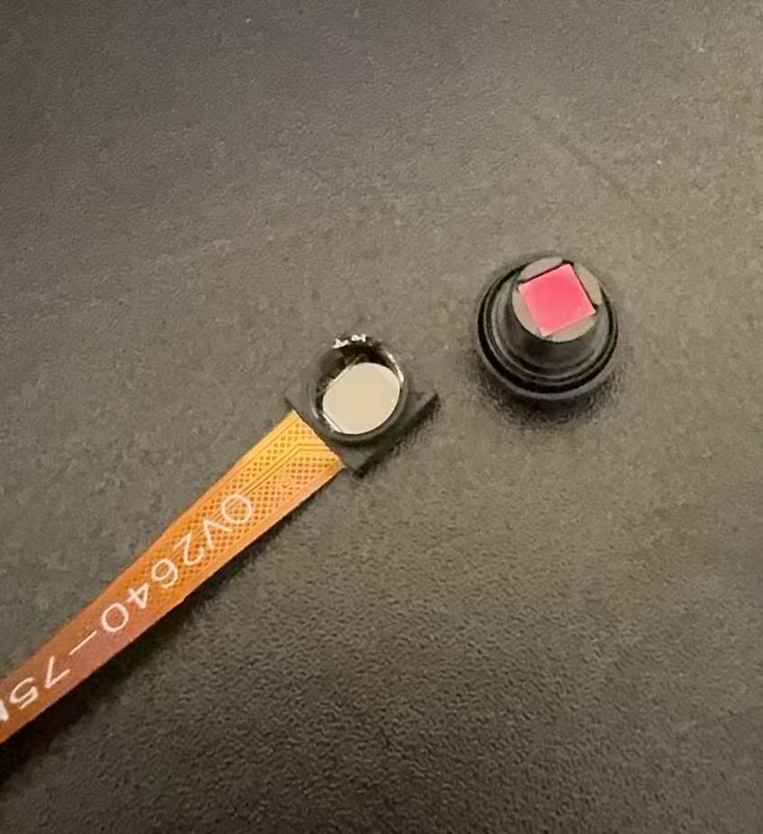
Minimum 2 IR-sensitive mini cameras (recommend purchasing 4 units, as IR filter removal carries risk of damage; ~$10-15 each)
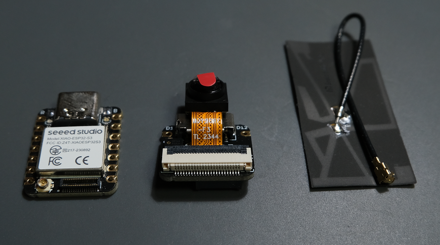
2 Microcontroller boards for image processing and data transmission (options include ESP32-CAM, Xiao ESP32S3 Sense; ~$15-25 each)
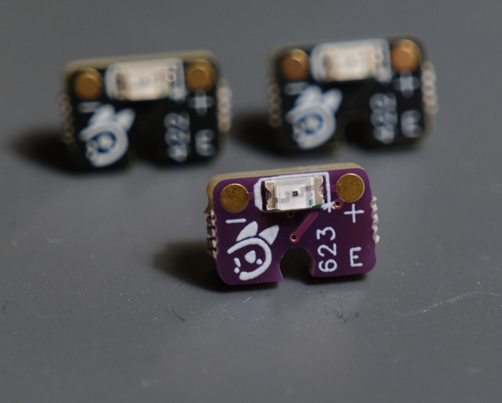
IR illumination system using 850nm wavelength IR LEDs (recommended: official LED set from EyeTrackVR with XL-3216HIRC-850; ~$20)
Additional Required Parts
- 3 USB-C to USB-C cables (2 for cameras, 1 for powering LEDs; ~$10-15 total)
- 3D printed mounting hardware for cameras, IR emitters, and microcontroller boards (~$5-10 if using a service, or material cost if self-printing)
- High-quality double-sided adhesive tape (preferably VHB or similar for secure mounting; ~$5-8)
- 1 roll of electrical tape for camera ribbon cable protection (~$3-5)
- Optional: Portable USB power bank for extended wireless operation (~$20-30)
Total estimated cost: $200-300 (excluding the VR headset)
Note: Most components are available through Amazon with rapid shipping. However, AliExpress offers significantly lower prices (see EyeTrackVR documentation for specific links). Be aware that AliExpress shipping typically takes 2-4 weeks, so plan accordingly if pursuing the more economical option.
Installation Notes
When following the EyeTrackVR documentation, pay special attention to these critical points:
1. Camera Ribbon Cable Fragility
⚠️ Notes: Minimize camera connection/disconnection cycles. After initial testing, it is highly recommended to immediately apply protective measures to the ribbon cable as outlined in the "Protecting a Camera Ribbon Cable" section. These ribbon connections are extremely delicate and prone to failure under repeated stress.
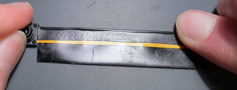
Figure 3: Apply electrical tape reinforcement to protect the camera ribbon cable.
2. Camera Positioning Optimization
My final version positions the cameras at approximately 45° angles relative to the eye plane, which:
- Reduces camera blind spots at extreme viewing angles and ensures consistent pupil visibility regardless of gaze direction
- Minimizes occlusion by facial features (cheeks, nose)
However, it is important to note that optimal camera angles may vary based on individual facial anatomy and headset fit. Experimentation with different angles is recommended to identify the best configuration for your specific use case.
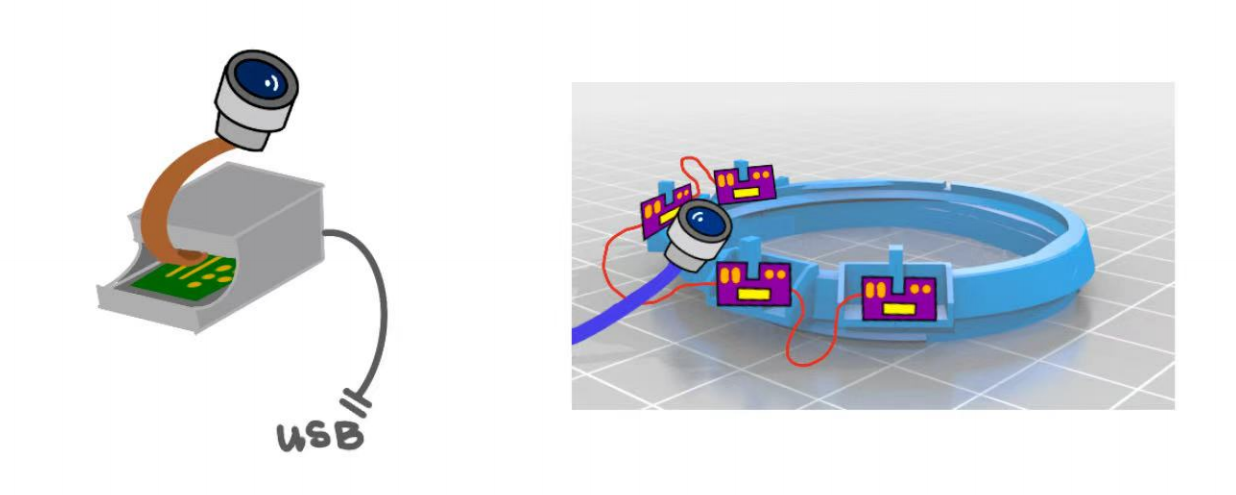
Figure 3: Camera positioning at 45° angles relative to the eye plane.
3. Cable Routing Strategy
Carefully plan your cable routing before permanent installation. The 3D printed camera mounts typically align the ribbon cable outlet with the USB-C port orientation. In this implementation, the camera ribbon was intentionally routed in the opposite direction of the USB-C cable to minimize cable congestion around the headset.
If adopting this approach, ensure thorough ribbon cable protection with electrical tape on both sides, and avoid any sharp bends in the ribbon. Gradual curves are essential for maintaining long-term reliability.

Figure 4: Camera mounting and cable routing example.
4. LED Circuit Orientation
When assembling the EyeTrackVR official LED arrays (V4 module design with 4 LEDs per eye), note that the circuits for left and right eyes are inverted relative to each other. This design consideration ensures proper IR illumination across the full visual field.
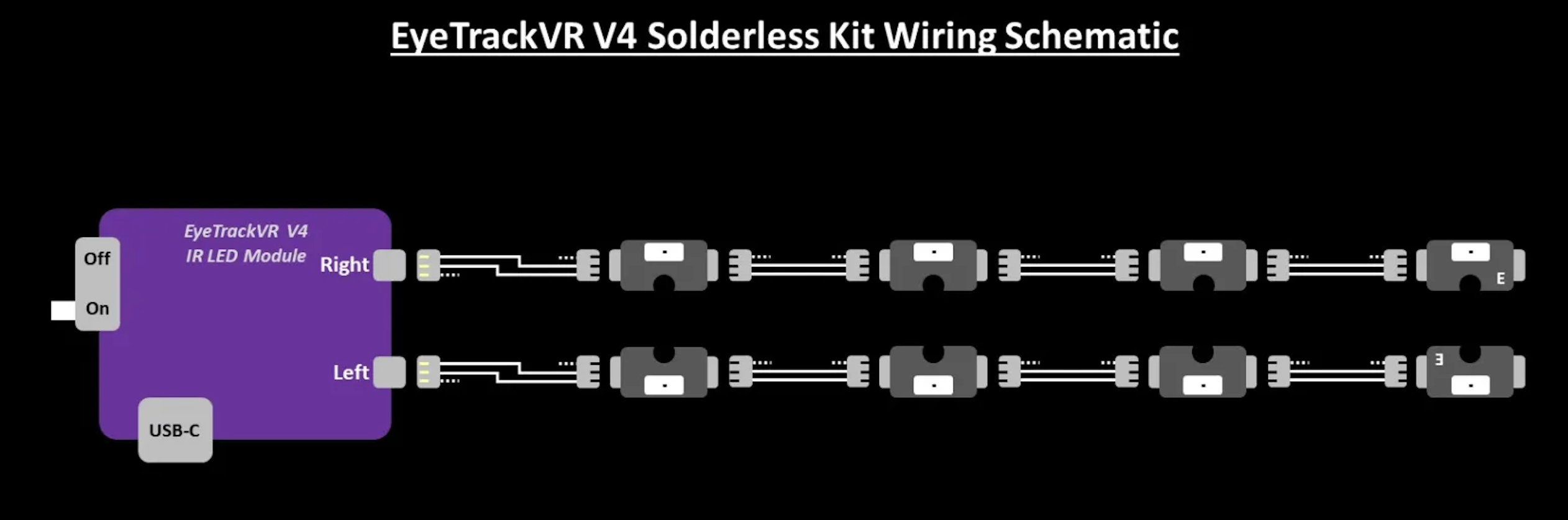
Figure 5: LED circuit orientation for left and right eyes.
⚠️ Notes: This prototype implementation relied on temporary mounting solutions using adhesives and tape to attach components to the headset. This rough build approach was chosen to facilitate rapid iteration and testing but likely impacts the overall accuracy and stability of the system. Future iterations should explore more permanent mounting solutions.
Firmware Installation
The microcontroller boards require appropriate firmware to function correctly. This implementation uses the wired configuration for its higher refresh rate, lower latency, and better stability.
Installation Steps:
- Download the firmware: Get the OpenIris firmware from the official GitHub repository
- Install development environment: Use Arduino IDE or PlatformIO
- Configure the firmware: Set parameters for your hardware:
- Camera type (OV2640, OV5640, etc.)
- Board type (ESP32-CAM or Xiao ESP32S3 Sense)
- Connection mode (Wired/Wireless)
- LED configuration and intensity
- Network settings if using wireless
- Flash the firmware to each microcontroller board using the Arduino IDE or PlatformIO
- Verify connectivity: Access the web interface at the IP address assigned to each board. Check that:
- IR LEDs illuminate (visible with phone camera)
- Camera feed appears in the web interface
- Pupil detection works by moving your eyes
Algorithm Selection: This implementation uses the Adaptive Starburst Hybrid Sample Feature (ASHSFRAC) algorithm for pupil detection and gaze estimation, which proved most effective in testing environments.
Troubleshooting tip: If experiencing connection issues, ensure your computer and the microcontroller boards are on the same WiFi network. Some institutional networks with client isolation may prevent proper communication. Consider using a dedicated WiFi router for the eye tracking system if necessary.
Unity Integration
A custom Unity program was developed for this project to handle calibration, validation, real-time visualization, and data collection.
Unity Program Features:
- OSC Communication: Receives real-time eye tracking data from EyeTrackVR firmware
- 9-Point Calibration System: With head movement compensation
- Validation Tools: Accuracy assessment and recalibration detection
- Gaze Visualization: Real-time visual feedback of gaze position
- Data Logging: Comprehensive recording with timestamps
- Heatmap Generation: Post-processing tools for attention analysis
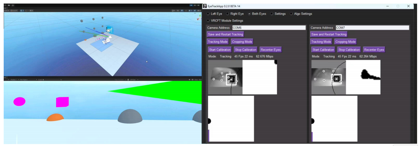
Figure 6: Unity calibration interface showing 9-point grid display (image placeholder).
Calibration Process:
The calibration algorithm creates a mapping between:
- Raw eye positions from tracker (normalized coordinates from EyeTrackVR's computer vision)
- Known positions of calibration points
- Head position and orientation in VR space
Validation and Accuracy Assessment:
After calibration, the system measures visual angle changes when shifting gaze between validation points and compares these with actual angular separations. This determines the "wiggle room" or error margin in tracking accuracy.
Recalibration Requirements: Testing showed that recalibration is typically needed after approximately 10 minutes of use, especially after significant head movements, headset adjustments, or changes in user posture.
Data Collection and Export:
The system logs comprehensive data for post-processing analysis including timestamps, gaze positions (2D screen and 3D world coordinates), head position/rotation, and eye openness. Data is exported in CSV format for easy analysis.
Performance Comparison
While this DIY solution cannot match the specifications of high-end commercial systems, it provides sufficient performance for many research applications at a fraction of the cost:
| System | Sampling Rate | Accuracy | Cost |
|---|---|---|---|
| EyeTrackVR (This Project) | ~60 Hz | 4.8° visual angle (SD = 1.8°) | ~$200-300 |
| Varjo XR-3 | 200 Hz | <0.5° visual angle | ~$6,500 |
| HTC Vive Pro Eye | 120 Hz | ~0.5-1.0° visual angle | ~$1,500 |
| Meta Quest Pro | 90 Hz | ~1° visual angle | ~$1,000 |
Challenges and Limitations
Several challenges and limitations were identified during implementation:
Hardware Challenges:
- Maintaining consistent IR illumination across different users with varying facial geometries
- Ensuring comfortable and secure mounting without permanent modification to VR headsets
- Cable management: The wired solution significantly constrains user movement, which should be considered in research design
- Camera occlusion when looking at extreme angles (though minimized with 45° camera positioning)
- Temporary mounting using adhesives/tape likely contributes significantly to accuracy limitations
Software Challenges:
- Frequent recalibration: Needed after approximately every 10 minutes of use or after significant head movements/headset adjustments
- Occasional software freezes (3-4 times per hour, 1-3 seconds each) likely caused by high USB data demand
- Need for occasional system reboots during extended sessions
Suitability Assessment:
These maintenance requirements indicate that the current implementation is better suited for exploratory research and early-stage demonstrations rather than extensive participant studies or rigorous data collection for publication. The system serves as an excellent educational tool and proof-of-concept platform.
Future Improvements
Several promising directions for future development were identified:
Hardware Improvements:
- Mounting System: The prototype's reliance on temporary adhesives likely contributes significantly to the 4.8° accuracy limitation. With more permanent and stable mounting solutions (custom-designed mounting brackets or integration with specific VR headset models), accuracy could potentially improve to 2-3° of visual angle.
- Multi-camera Solutions: Explore additional camera angles to reduce blind spots when looking at extreme angles
- Modular IR Illumination: Develop systems that better adapt to different users and facial geometries
- Improved Wire Management: Create more elegant cable routing solutions
Software Improvements:
- Investigate alternative computer vision algorithms that might improve accuracy while maintaining 60Hz refresh rate
- Implement continuous calibration mechanisms to reduce the need for manual recalibration
- Optimize data throughput to prevent occasional freezes
- Develop better diagnostic tools for troubleshooting
Conclusion
This project demonstrates that affordable, open-source eye tracking solutions can be successfully implemented for VR research applications. While commercial systems offer higher specifications, this approach dramatically reduces the barrier to entry for eye-tracking research, making it accessible to a wider range of institutions and independent researchers.